Choosing the correct type of the conveyor for any given application depends on a number of factors including material characteristics, conveyor system layout, duty, environment, etc.
The following graph has been developed to assist learners with the selection of the correct type of belt conveyor system. This graph is intended for use as a guide only and Users would be well advised to approach suppliers of these conveyor systems in order to confirm whether the preferred type of conveyor is appropriate.

Conveyor Selection Criteria
For the novice, a brief outline of the basic considerations and limitations of the troughed belt conveyor are given below. Reference is also made to alternative types of belt conveyors which may be more suitable than troughed belt conveyors in some instances.
As can be seen below, it is incumbent on the engineer to establish the most cost-effective and practical conveyor system in each application. Where necessary visitors should consult the appropriate sections dealing with these alternative types of conveyors by clicking on the title bar at the top of your screen.
Note that detailed design by a competent engineer is required to establish the specific layout parameters for each conveyor. The information provided below serves merely as a guide.
i Layout
| For 'short' troughed belt conveyors (whose length is less than approximately 500 m) and troughed belt conveyors installed in factories or plants should be straight in plan view. These conveyors may be inclined, horizontal or declined in elevation, or parts of a conveyor may be inclined, horizontal and declined. |  |
For 'long' troughed belt conveyors (where the conveyors' length is in excess of 500 m) and where the conveyor is an overland-type conveyor following ground line, horizontal curves of radius greater than 1000 m can be considered.
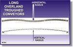 | As above, these conveyors may include inclined sections, horizontal sections and declined portions between the loading and discharge points. |
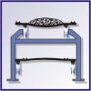
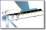 | At loading points, the maximum inclination of the belt should not be greater than approximately 5 degrees to the horizontal. This maximum inclination is dependent on the belt speed, the material characteristics and to a lesser degree the layout of the feed point. Inclining the loading point to a greater angle may result in spillage at the loading chute. |
A further consideration at loading points is the height required above the conveyor belt for the loading chute work. It is important that material is loaded onto the center of the conveyor belt to ensure that the belt runs centrally along the conveyor structure. To achieve this the loading/feed chute must be wide enough at the top of the chute to collect all material being fed into it, while the bottom of the chute must be no wider than 2/3 of the width of the conveyor belt.
 | The side walls of the chute must be steep enough to prevent material accumulating on the side walls and corners of the chute, which could lead to blockages. Typically side walls of chutes range between 45 degrees and 70 degrees depending on the material to be conveyed. |
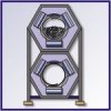
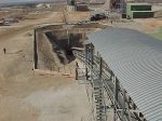
It can be seen in the sketch therefore that careful consideration must be given to the layout of the tail station. The height required above the new conveyor belt for the feeding system and chute work must not be overlooked.
The discharge of material from a troughed belt conveyor is usually via a chute onto another conveyor, into a silo, etc. As with the feed chute, the discharge chute must be carefully laid out in order to establish the required elevation of the head / discharge pulley to ensure that the discharge chute does not block under full load conditions.
It has been explained above that troughed belt conveyors are generally designed as straight conveyors (plan view), certainly in the case of short belt conveyors. When a designer is considering the layout of a conveyor in a factory for example, the desired route which the conveyor is to follow may not in fact be possible due to physical obstacles located between the feed point and the desired discharge point.
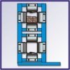
 | In such a case the designer is presented with a number of options which should be investigated prior to finalising the design of the belt conveyor system to be used. |
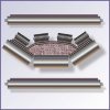
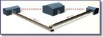
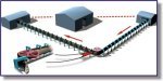
A first option may be to use two a troughed belt conveyors with a transfer point between the two conveyors, as can be seen in this sketch.
A second option may be to use a different type of belt conveyor for example the pipe conveyor or Sicon conveyor which offer the ability to negotiate corners without the need of transfer points. Each of these alternative types of belt conveyors has their own layout constrains, advantages and disadvantages, which the designer must take into consideration as part of the investigation.
The inclination of a belt conveyor is also a factor which must be considered by the engineer, when selecting the type of belt conveyor to be used. The maximum inclination or decline of a conveyor generally depends on the characteristics of the material to be transported.
ii Conveyor Duty & Material Specification
It is important that the duty which the conveyor is expected to fulfill is clearly established at the commencement of the design phase, as this will impact on numerous items in the detailed design of the conveyor and component selection.
The capacity of the conveyor (in tons per hour or cubic meters per hour) as well as the average operating hours per day or per year are important design criteria.
Details pertaining to the material to be conveyed must also be specified.
Having established the duty that the conveyor is expected to fulfill and obtained the material specifications the designer is in a better position to determine the most cost-effective conveying method to be employed.
iii Environmental Considerations
The need to improve the local environment at factories and plants is gaining support throughout the world and is often driven by legislation. As such the type, layout, design and correct operation of belt conveyors and their associated equipment is becoming more important.
Environmental considerations cover an extremely wide scope of issues ranging from the degree of pollutants generated by the working conveyor to the visual impact of a conveyor on the local community. The designer cannot therefore neglect to include the environmental considerations into the assessment of the most appropriate type of conveyor.
Environmental legislation differs from country to country and from factory to factory and it is therefore important that the specific environmental legislation and rules be established and introduced into the overall conveyor feasibility and design procedure.
For the purposes of list Beginners Guide, some of the most obvious environmental-related issues are itemised below to provide the learner with an holistic approach to conveyor design.
Products which are dusty or which tend to generate dust at transfer points for example powder cement and dry fly ash, may be conveyed in enclosed conveyors. Examples of enclosed conveyors include pipe conveyors, Sicon conveyors, bucket elevators, screw conveyors and pneumatic transportation systems.
In considering the layout of the conveying system, the number of transfer points between conveyors should be minimised to reduce the number of dust and spillage generating points in a conveying system, thereby minimising the impact of the system on the local environment.
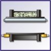
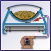
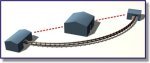
Using a pipe conveyor which incorporates a gradual 90 degree curve can eliminate one transfer point in an equivalent troughed belt conveyor system, where two troughed conveyors would otherwise be necessary.
|
|  |
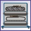
Alternatively, a Sicon conveyor may be a better solution due to its superior cornering ability and increased flexibility.
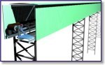
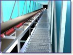
Should a troughed belt conveyor be used however, the conveyor can be installed into an enclosed gantry or tunnel to reduce the possibility of material being blown off of the carrying side. Covers can also be installed over the carrying belt to reduce the risk of material blowing off of the conveyor and / or contain the dust.
The environment in which the belt conveyor is to operate may be subject to extreme variations in weather conditions. A conveyor located on a jetty for example, may be subject to high and low temperatures, strong wind conditions and an extremely corrosive environment. In such a case issues such as whether or not the conveyor is to be enclosed becomes extremely important. In addition, the materials of construction of the structure may be different to an equivalent conveyor located in a dry, noncorrosive environment. The corrosion protection specification applicable to the conveyor structure and components would typically demand a far greater degree of control over the application and maintenance of the coating.
The material to be conveyed may inherently be a commodity of high value where the client wishes to limit access to the product and the opportunity for spillage. The transportation of diamond-bearing Kimberlite to and from a process plant is an example of such an environment. In such a case Sicon conveyors are employed for their ability to negotiate difficult conveying routes without the need for transfer points as well as the fact that they enclose the material.
The 'environment' in which a conveyor is to be installed may dictate that the space available for a conveyor is extremely limited. Transporting material from ground level to the top of a bin or silo may require the conveyor to be installed vertically up the side of the silo. In this case the equipment to be used would typically be a bucket elevator or a pocket belt or a sandwich type conveyor, all of which are able to transport material vertically.

The location of the site where the conveyor is to be installed may be in a cold, mountainous area. In this case (assuming ambient temperatures drop to well below freezing), special consideration must be given to the selection of the conveyor belt as well as to items such as the mechanical components (bearings) and the lubricant proposed. Starting belt conveyors in extremely cold conditions requires among other things additional power to overcome the friction imposed by cold lubricants and a stiffer belt.
| In addition to the temperature aspect, it may be necessary to route the conveyor down the side of a mountain and the conveyor route must negotiate the natural contours of the terrain thereby forcing the designer to incorporate vertical and horizontal curves into the conveyor layout. Where the environment imposes extremely arduous parameters/limitations on the design of the conveying system, it may be necessary to reconsider whether in fact a belt conveyor is appropriate for the application. | 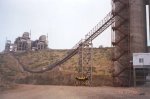
|
iv Cost
Like any other equipment, there are costs associated with belt conveyors and these costs must be determined to a reasonable degree of accuracy in order for a commercial evaluation to be developed which will accompany the technical evaluation.
It is generally accepted practice for the 'costs' of a conveyor to be presented in two categories namely; the initial capital outlay or capital expenditure for the system i.e. CAPEX and an ongoing operating and maintenance expense i.e. OPEX which the client will incur for the remaining life of the conveyor system.
CAPEX should take into consideration costs such as :-
the cost of the mechanical, electrical, civil, structural and instrumentation equipment purchased and installed on site as part of the conveyor.
the project management fee which a contractor / supplier will charge the user for executing the project.
the cost of any modifications to existing equipment which may be required on site to incorporate the new conveyor into the factory.
the cost to install, commission and test the conveyor system on site.
OPEX should take into consideration the following costs :-
the cost of spare parts which the user will have to procure over the operational life of the conveyor. This cost is based on a projection of the life of components within the conveyor and the cost of each of those components, based on the duty of the conveyor.
the cost of personnel required to operate the conveyor.
the costs of personnel and equipment required to maintain the conveyor.
the cost of electrical power to drive the conveyor.
Depending on the layout of the conveyor system and possibly the type of conveyor system to be used, the CAPEX and OPEX costs will differ. It is important therefore that the calculation of the costs for each option is performed according to the same basic parameters for example, similar costs for man hours and for electric power.
It is possible for the total life cycle costs (CAPEX and OPEX) for any given option to be represented in a number of ways. Examples include; all capital and operational costs may be shown as a present value cost, escalation and/or discount factors may be included or excluded from the financial analysis, etc.
v Standardisation
If a belt conveyor is to be installed on either a new plant or existing facility, the choice of type of conveyor to be used may depend to a large extent on the need to standardise on the type of equipment used.
In the case of a new factory for example where a number of troughed belt conveyors are to be used throughout the facility then, in the interests of standardising and minimizing on spares to be held by the client and the training of personnel to operate and maintain the conveyors, the type of conveyor to be used should as far as reasonably possible be kept the same.
Notwithstanding the need to investigate the optimum layout and cost for a particular conveyor, practicality dictates that standardisation of equipment is very often in the long-term interest of the end-user of the equipment and the engineer should bear this in mind in his assessment.